SC Dimmer RGBW
SC Dimmer RGBW A1 is a four-channel 12-24 V PWM controller for analog RGBW LED strips in the Spectoda ecosystem.
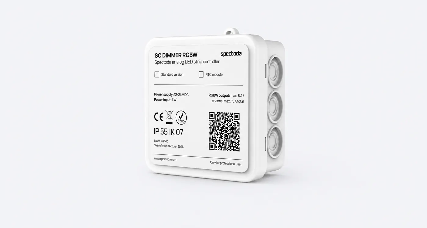
The current technical model of this branch is SC Dimmer RGBW A1.
Description
Section titled “Description”SC Dimmer RGBW is a four-channel PWM controller from the Spectoda ecosystem for analog RGBW LED strips powered from a 12-24 V DC source. The product code of the current revision is SPE10104C-X-IA-0400.
This page describes the pre-production state of revision A1 from June 9, 2026. The materials are intended for preparing the cabinet, cabling, mechanical mounting, and technical inspection of the first production series.
SC Dimmer RGBW uses the common positive conductor of the LED strip and separately switched negative channels R, G, B, and W. The controller is intended for installations where an analog RGBW LED strip should be controlled directly from the Spectoda environment.
Use within the Spectoda ecosystem
Section titled “Use within the Spectoda ecosystem”- architectural RGB/RGBW LED strips
- cabinet-based control of multiple LED branches
- installations with local protection of individual channels
- projects connected to the wireless Spectoda ecosystem
Key features
Section titled “Key features”- 4 separate PWM outputs for an analog RGBW LED strip
- input voltage
12-24 V DC - input MINI automotive blade fuse
15 A - channel MINI automotive blade fuses
5 A - RGB mode max.
15 Acumulatively across the whole controller - RGBW mode typically max.
10 A, becauseWis calculated from RGB and no more than two 5 A channels run at the same time - service button, status LED, and service pin header
Supported LED strips
Section titled “Supported LED strips”Analog RGB/RGBW LED strips controlled through separate channels and a common positive LED conductor.
Technical specifications
Section titled “Technical specifications”| Specification | Type / value |
|---|---|
| Product code | SPE10104C-X-IA-0400 |
| Technical variant | SC Dimmer RGBW A1 |
| Input voltage | 12-24 V DC |
| Output topology | low-side PWM for common positive LED conductor |
| Number of channels | 4 |
| Input protection | MINI automotive blade 15 A |
| Channel protection | MINI automotive blade 5 A per channel |
| Power consumption | 1 W |
The fuse size used is MINI / MINIVAL 11.1 mm. Standard 19 mm ATO/UNIVAL fuses are not mechanically compatible with the holders in this revision.
Mechanical specifications
Section titled “Mechanical specifications”| Parameter | Value |
|---|---|
| PCB footprint | 71.9 x 53.6 mm according to the dimensioned drawing |
| Control dimensions from drawing | 36.1 mm, 15.0 mm, 35.0 mm |
| Recommended installation space | Spelsberg i 12-L, 85.0 x 85.0 x 37.0 mm |
| Recommended enclosure | Spelsberg i 12-L, product number 33291201 |
| Enclosure | 85.0 x 85.0 x 37.0 mm, IP55, IK07 |
Connection interfaces
Section titled “Connection interfaces”| Terminal / element | Function |
|---|---|
INPUT + | positive pole of the 12-24 V DC source |
INPUT - | negative pole of the source |
+ | common positive LED strip conductor |
R | switched negative channel of the red branch |
G | switched negative channel of the green branch |
B | switched negative channel of the blue branch |
W | switched negative channel of the white branch |
The 15 A limit is the total limit of the whole controller and also matches the maximum current of the terminals used. The device is not intended for long-term operation at 4 x 5 A simultaneously.
Installation instructions
Section titled “Installation instructions”The controller is intended for mounting on insulating standoffs inside a cabinet or a suitable enclosure for the whole assembly. The recommended installation enclosure is Spelsberg i 12-L (33291201), the same type as for SC Industry.
The bottom side of the PCB must not touch a metal base plate or DIN rail. In the cabinet design, leave access to the terminals, service button, and all five MINI blade fuses.
The board footprint 71.9 x 53.6 mm corresponds to the same mechanical family as SC Industry A, whose footprint is listed in materials as 72 x 54 mm.
Wiring diagram
Section titled “Wiring diagram”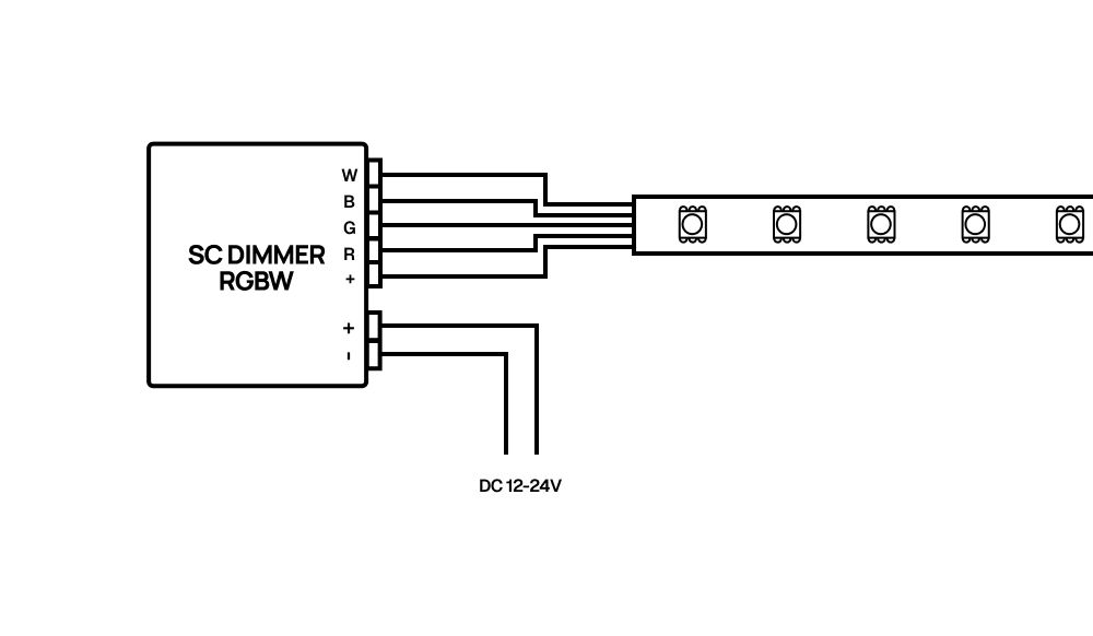
Electrical specifications
Section titled “Electrical specifications”Absolute maximum ratings
Section titled “Absolute maximum ratings”| Parameter | Min | Typ | Max | Unit |
|---|---|---|---|---|
| Input power | 12 | - | 24 | V DC |
| Current load | - | - | 15 | A |
| Current load per channel | - | - | 5 | A |
Recommended operating conditions
Section titled “Recommended operating conditions”| Parameter | Min | Typ | Max | Unit |
|---|---|---|---|---|
| Input power | 12 | - | 24 | V DC |
| Maximum current per channel | - | - | 5 | A |
| RGB mode | - | - | 15 | A cumulative |
| RGBW mode | - | - | 10 | A typical |
| Operating temperature | -20 | - | +60 | degC |
| Storage temperature | -25 | - | +70 | degC |
Visualization
Section titled “Visualization”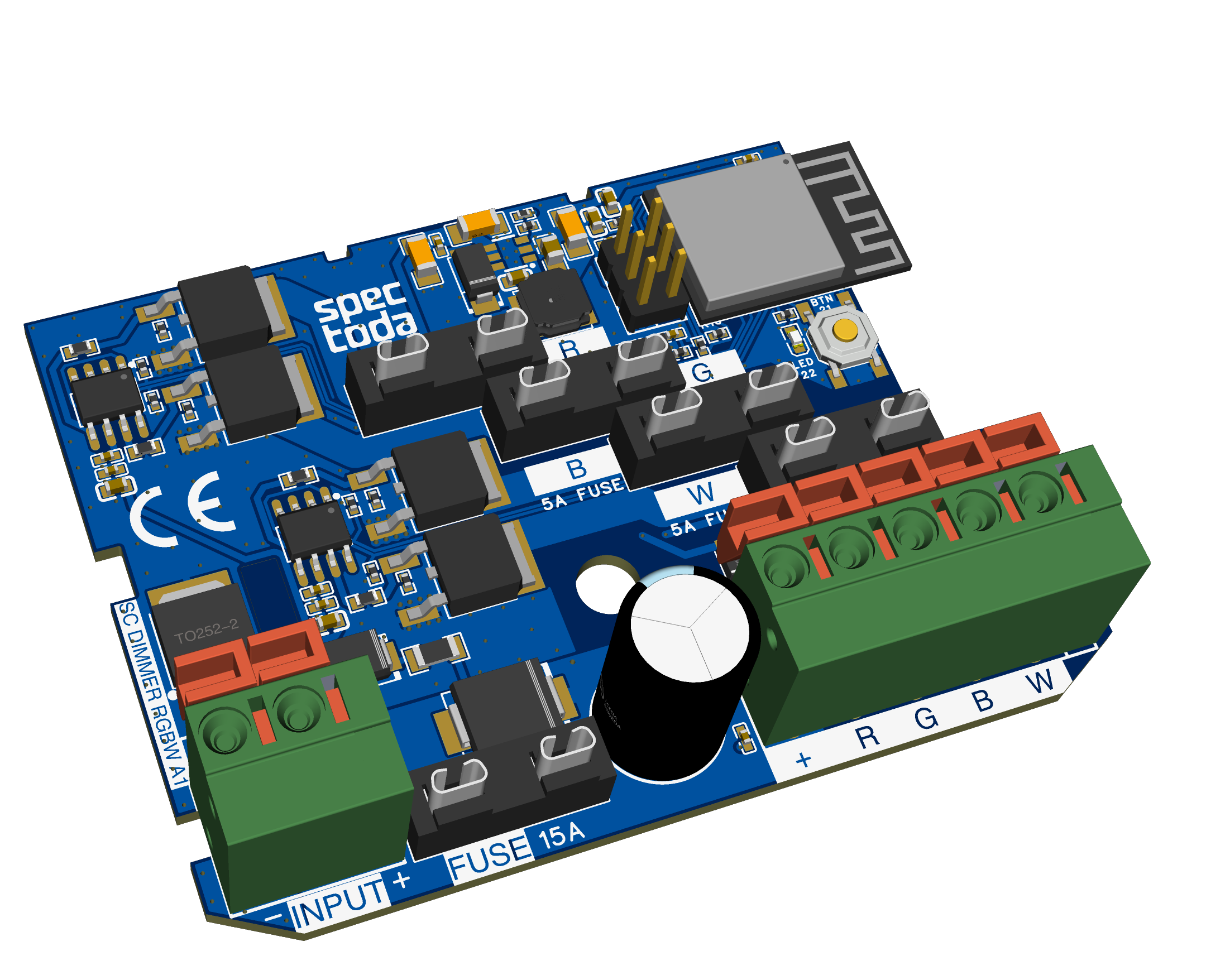
Safety
Section titled “Safety”- The bottom side of the PCB must not touch a metal base plate or DIN rail.
- In the cabinet design, leave access to the terminals, service button, and all five MINI blade fuses.
- Leave space above the power section and fuses for airflow.
- The temperature rating will be confirmed after testing the first production series under real load.
- The device is not intended for long-term operation at
4 x 5 Asimultaneously.
Additional information
Section titled “Additional information”More technical data is available from:
SC Dimmer RGBW A1 - Datasheet 2026 EN.pdf
SC Dimmer RGBW A1 - User manual 2026 EN.pdf
SC Dimmer RGBW - CE - 2026.pdf